
Hall Effect tækjabúnaður
PASSE7260
Lýsing
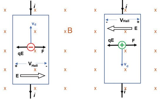
The Hall Effect experiment (conducted by Edwin Hall in 1879) determines the sign of the charge carriers in current flow. A current can be thought of as a negative charge moving in one direction (Figure 1) or as a positive charge moving in the opposite direction (Figure 2). To determine which it actually is, a semiconductor is immersed in a magnetic field transverse to the direction of the flow of current.
The moving charge experiences a qv x B force, causing a charge build up on one side of the semiconductor (creating an electric field), which in turn leads to a qE force. The direction of the electric field will depend on the sign of the charge carriers and the polarity of the Hall voltage across the semiconductor reveals the sign.
The magnitude of theThe PASCO Advantage
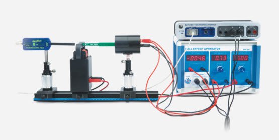
The open design of this Hall Effect apparatus makes it possible for students to see the direction of the current and the magnetic field, enabling them to use the sign of the Hall voltage to deduce the sign of the charge carriers.
Figure 1 and Figure 2
Special Features
Variable magnetic field and current
Open design makes the current direction clear
Works with the 550 or 850 Universal Interfaces
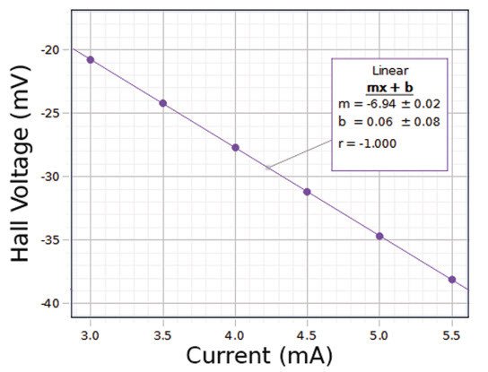
Hall voltage is dependent on the current, the charge carrier density, and the magnitude of the electric field. In modern day electronics the Hall effect is used to measure the magnitude and direction of magnetic fields.
Includes
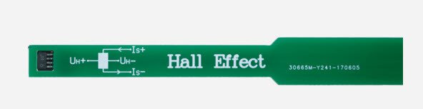
Hall Probe Unit, n-Semiconductor (GaAs)
Hall Effect Power Supply
U-Core Electromagnetic Coil
Track, Length 40 cm
Optical Carrier (2)
Adjustable Post Holder with 9 cm post (2)
Banana Cords (6)
Connecting Cables for 550/850 Interface (2)
Manual
Specifications
n-Doped Semiconductor Material
GaAs
Hall sensitivity
= 150 mV/(mA·T)
U-Core Electromagnetic Coil
1000 Turns
Magnet Space
10 mm
Magnet Field
0 to 0.065 T (at 1 A)
Excitation Current
0 to 1 A DC
Hall Voltage
0 to 1.9999 V
Power Supply
Digital readout for Current, Hall Voltage, and Magnet Current
The moving charge experiences a qv x B force, causing a charge build up on one side of the semiconductor (creating an electric field), which in turn leads to a qE force. The direction of the electric field will depend on the sign of the charge carriers and the polarity of the Hall voltage across the semiconductor reveals the sign.
The magnitude of theThe PASCO Advantage
The open design of this Hall Effect apparatus makes it possible for students to see the direction of the current and the magnetic field, enabling them to use the sign of the Hall voltage to deduce the sign of the charge carriers.
Figure 1 and Figure 2
Special Features
Variable magnetic field and current
Open design makes the current direction clear
Works with the 550 or 850 Universal Interfaces
Hall voltage is dependent on the current, the charge carrier density, and the magnitude of the electric field. In modern day electronics the Hall effect is used to measure the magnitude and direction of magnetic fields.
Includes
Hall Probe Unit, n-Semiconductor (GaAs)
Hall Effect Power Supply
U-Core Electromagnetic Coil
Track, Length 40 cm
Optical Carrier (2)
Adjustable Post Holder with 9 cm post (2)
Banana Cords (6)
Connecting Cables for 550/850 Interface (2)
Manual
Specifications
n-Doped Semiconductor Material
GaAs
Hall sensitivity
= 150 mV/(mA·T)
U-Core Electromagnetic Coil
1000 Turns
Magnet Space
10 mm
Magnet Field
0 to 0.065 T (at 1 A)
Excitation Current
0 to 1 A DC
Hall Voltage
0 to 1.9999 V
Power Supply
Digital readout for Current, Hall Voltage, and Magnet Current